DCC transformation of the 2006 Walthers/Life-Like GP38-2
Last updated on: 2022-02-07
DCC transformation of the 2006 Walthers/Life-Like GP38-2
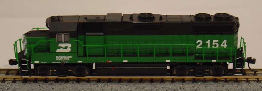
Life-Like '2006' GP38-2
A not-so-DCC-friendly model
Though there is no mention of it on the box, the commercial claim when the Life-Like N scale GP38-2 was re-released in 2006, was that the locomotive was ‘DCC Friendly’ in the sense that it had a split frame and a PC (Printed Circuit) board. Yes but, the point is that the bottom motor contact is … at the bottom, i.e. without any metallic strip bringing it upwards and that the motor contacts go directly to the frame and not the PC board! Therefore, no DCC manufacturer ever designed a replacement board for it.
In comparison, on Atlas models of the same vintage, the two motor contacts are available on the top and they are connected to the analog PC board, ready for a DCC replacement board. The motor is powered from the PC board that is itself connected to the two half-frames. Moreover, the motor is perfectly insulated from the chassis.
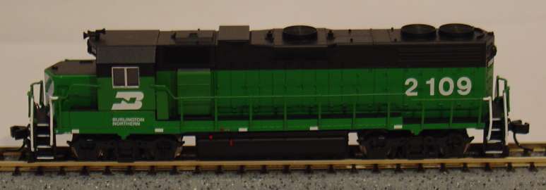
Atlas '2007' GP38-2

Image courtesy of TCS
On the Life-Like model, the PC board is only a light board and I think that its purpose is to dim lights opposite to the direction of travel.
So, transforming this engine to DCC is not going to be a piece of cake. The first method that you’d think about is to insulate the motor and wire a decoder to it and to the light board, after some modification of the light board. This is exactly the way that our fellow TroveStar curator Brad Myers did: see on his web-site.
Actually, as the Life-Like PC board is having some similarity with the analog PC board of Atlas locomotives, I figured out that I could save myself understanding the logic of the Life-Like board, and wire a decoder on the Atlas board that is much simpler. I have plenty of those analog Atlas PCBs as I have installed DCC replacement boards in all my engines.
So, this is what I did, at the expense of several modifications to the frame though.
One year after, re-thinking about it, I replaced the whole thing by a DCC replacement board that I had recuperated in an Atlas locomotive. This is actually even simpler, and probably the easiest method to transform this engine to DCC.
Both methods are described hereafter. You will need a cutting and a grinding tool. I recommend to use a rotary tool such as a Dremel®. And of course, you will need a soldering iron and the associated accessories.
First method: use an Atlas analog PC board
The Atlas PCB can be taken from any Atlas locomotive where you’d put a Digitrax DN163A0, a TCS AMD4 or a NCE N12A0, i.e. nearly all of them!
First step
Now let’s have a look. The Atlas and the Like-Like boards have almost the same external size, but the contacts to the chassis are not positioned the same way.
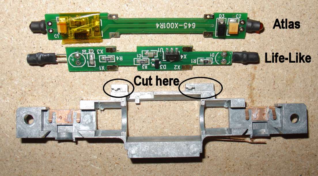
So, let’s go and cut the upper part of both half-frames as shown on the picture.
Second step
Now surgery is over; it should look like on this picture. I have removed also some metal from the small side notch to ease further insertion of the PCB.
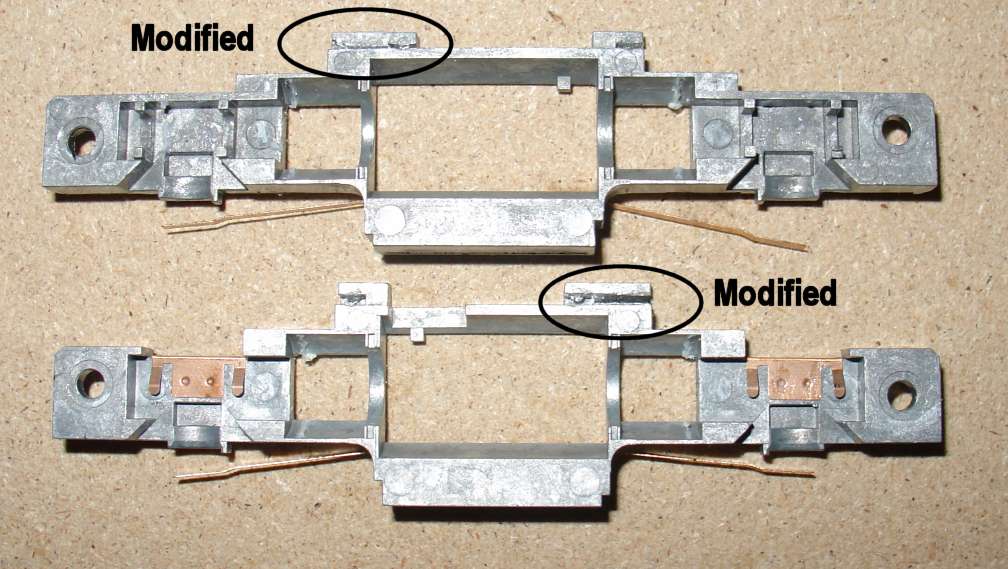
Third step – modification of the Atlas PCB
Not much to do, but to cut the traces on the resistor side of the LEDs.

I made a first attempt by removing all capacitors and diodes, but it was not conclusive (false contacts, flicker, etc.). Finally, it works very well by leaving everything as is.
Fourth step – motor contacts
Two wires (orange and gray) are soldered to the motor contacts, and raised upwards.
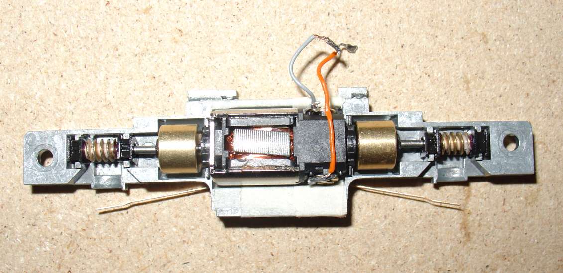
It is of the utmost importance to perfectly insulate the chassis from the motor contacts. So, don’t be shy with insulating tape.
Fifth step – Re-assembly
After reassembling the two half-frames, you can see that there is room enough at the rear below the PCB to insert the decoder (here a Kuehn N025) – Insulate properly the decoder from the chassis and from LED PCB with a piece of insulating tape.
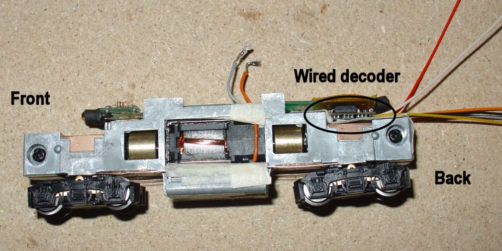
Sixth step – Connect the decoder’s wires
Then you can wire the decoder as indicated on the image:
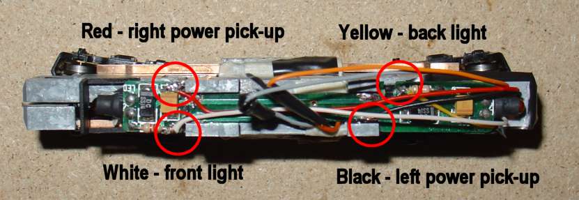
On the PCB: red and black wires for power pick-up, white and yellow wires for the front and rear lights.
For the motor: connect the orange and gray wires from the motor to the wires of the same color on the decoder side.
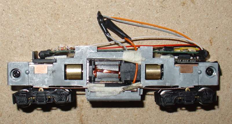
You need to cut the wires at the appropriate length and solder each one at the indicated place. Note that I probably have left too much length on the wires, but it fits under the shell, so be it.
Also note that I had initially used painter’s masking tape as insulating material. That is not a good idea as it is ageing badly and deteriorating with the heat of the motor. The best is the Kapton tape, but if you don’t have some, regular electrical insulating tape will do.
The Kuehn decoder does not have a blue wire (common / ground for lights). In case you have a decoder with a blue wire, connect it to the black wire.
Second method: use a DCC replacement board
First step
You’ll need to cut the upper part of the half-frames just like in steps 1 and 2 of the first method.
Second step
You need to do a bit more surgery by removing metal from the top of the half frames (see picture).
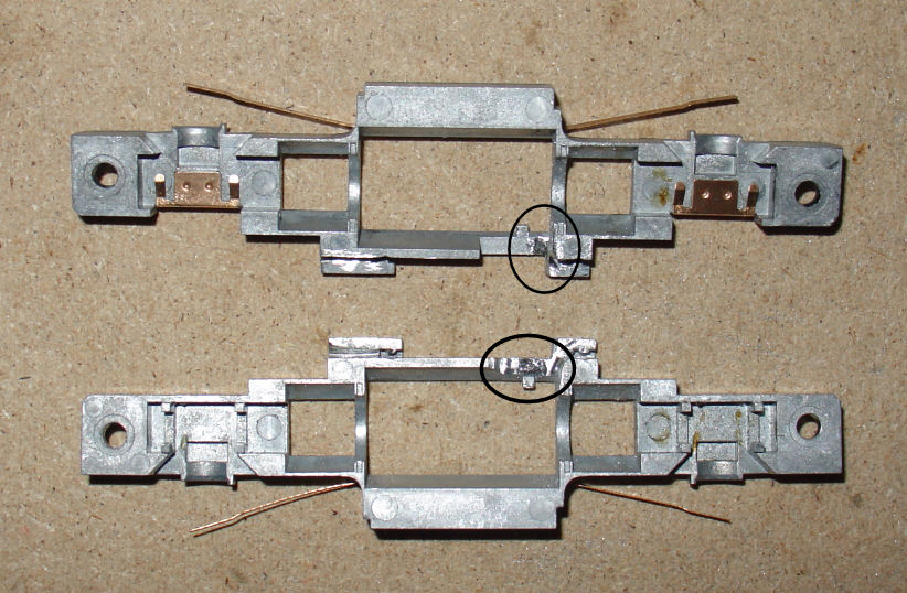
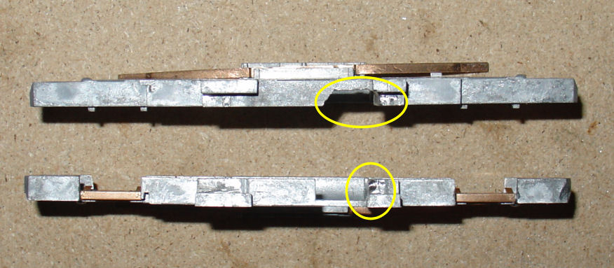
This is actually necessary to create room for the two contacts located under the replacement board, and to prevent them from touching the chassis, and also to create a passage for the motor wires.
Third step
Prepare your decoder by soldering one gray and one orange wire to each motor contact of the board.
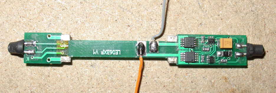
For this method I have re-used a Lenz decoder LE063XF that was factory-mounted in another Atlas locomotive; but the method would apply with any of the replacement boards for Atlas engines that I have listed above. The LE063XF is an old generation decoder without Back Electro-Motive Force (BEMF), but considering the price I paid for the Life-Like engine, that is good enough.
Fourth step
All parts (chassis and motor) must be well insulated before reassembly.
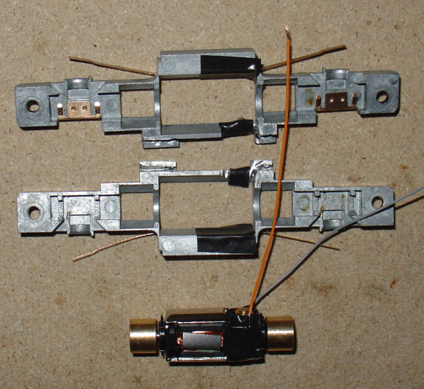
I folded the two strips of motor contacts along the motor before soldering the wires, in order to limit the temptations of a short-circuit; and used abundantly insulating tape (one is never too careful).
Fifth step
Re-assemble everything and solder the wires from the motor to the wires connected to the motor contacts of the PCB. It is much easier to do it like I show rather than attempting to solder directly from the motor to the motor contact on the board. Then insulate the soldered junction and fold everything back on the top of the board. Put the shell back on, and here you go!
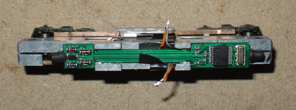
Note that – shame on me – I inverted the motor wires. I could actually have change the direction of travel in CV29 of the decoder, but I preferred to invert the wires…
As expected the Lenz decoder is working, but not very brilliantly. So, prefer to use a more modern decoder. The engine actually deserves it and will be an excellent runner in DCC after this little ‘plastic surgery’.
Credits
The copyright of this article is held by Alain LM, who is granting TroveStar with right to display it. This is a modified version, translated in English, of a thread that I published in 2008 and 2009 on ‘Le forum US’, a French forum dedicated to North-American railroad modelling.
Except otherwise mentioned, all images are copyrighted by the author.

