50 Shades of DCC Ready
Last updated on: 2021-08-18

50 Shades of DCC Ready
Not sure just how “ready” or “friendly” some so-called ‘DCC Ready’ or ‘DCC Friendly’ locos are? You are not alone.
For more than a decade, I have added dozens of these small micro-controller chips (called DCC decoders) to my engines and learned a thing or two. Perhaps the most important thing I have learned is this: adding a decoder to a "DCC ready" loco is by no means rocket science but it is also not as easy as some manufacturers would have you believe.
I thought I would share some of my experience with decoder form factors, drop-in decoders and plug decoders to help de-mystify all of this. I hope you find this article helpful.
Before I continue, let’s talk about terminology and some installation basics (ie what’s necessary for a model to even fall into the Ready or Friendly category).
There are several ways to rank how easy it is to install a DCC decoder into a loco and I define these terms below. The TroveStar N Scale Model Trains Database uses ‘Ready’ and ‘Friendly.’ Other reference sites use additional terms, such as ‘Plug’N’Play’ and ‘Ready/Difficult.’
In order to install a DCC decoder, the motor must be fully isolated from the track power. As very often the track power is going through the chassis, another way to say it is that the motor must be isolated from the chassis. If this is not the case, installing a DCC decoder might require quite a few modifications, which would make a model of this type neither Ready nor Friendly.
Commonly agreed-upon definitions
Friendly
This means the locomotive’s motor is isolated from the chassis and from the track power.
Unfortunately, Friendly does not mean much more than this. So most likely, in order to install the microchip into your loco, you’ll have to solder the decoder’s wires as best you can, make room for the decoder (by removing some part of the chassis) and modify the connection of the front and back lights (if any exist).
Ready
Ready can mean a number of things, ranging from very close to the ‘Friendly’ definition (above) to very easy, such as plugging in a NMRA 6-pin (NEM651) decoder. I provide a number of examples (below) to illustrate this range.
In the TroveStar database, for each type of locomotive, you will find a DCC section that will provide you with all the necessary information with regards to the DCC readiness level and useful links to DCC manufacturer’s information page.
Plug’N’Play
As the title suggests, this means the decoder simply has to be ‘plugged in.’ Some manufacturers also use the terms ’Drop-in’ or ‘Plug-in’ to describe these kinds of decoders. There are two major types of Plug’N’Play decoders: (1) replacement boards and (2) ‘plug’ decoders (with a number of pins). Terms like drop-in and plug-in may lead you to believe that these decoders are in fact easy to use, but this is by far not always the case.
We don’t use this ranking in TroveStar; all such decoders will fall into the ‘Ready’ category.
Decoder form factors
DCC decoders come in three different types of form factors: wired, plug and replacement board.
Wired
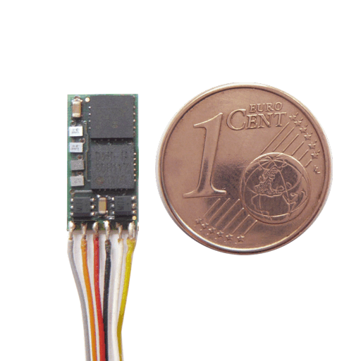
Wired decoders are the ‘Swiss-army knife’ type of decoder. They come in multiple sizes and different levels of complexity, which is usually reflected by the number of wires they contain. A minimum of six wires is needed to control the front and back lights – and the motor of course. More wires means more functions can be controlled. Sound decoders obviously require more wires to control the speaker and the cam drive for steam engines. In certain instances, it is better to use Z scale (the smallest size) wired decoders for more ‘difficult’ cases.
To learn more, I highly recommend the excellent web-site of our fellow TroveStar curator Brad Myers (a.k.a. NScaleStation) where you can find many examples of wired decoder installs: http://n-scale-dcc.blogspot.com/
Plug
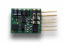
Decoders with plugs are probably the easiest to install. Similar to wired decoders, the minimum is 6-pin decoder, that is standardized as (European) NEM-651 (NEM 651 Elektrische Schnittstelle - Ausführung Klein (S)) or (North American) NMRA small 6-pin (S-9.1.1 Connectors). The good news about these basic 6-pin decoders is that they are truly universal and offered by many suppliers.
I myself have installed several Digitrax DZ125IN in European models that perform perfectly with European control stations. Most of the European models will come with a NEM651 interface.
In some cases, there might be some mechanical issues (as the decoder could have the tendency to disconnect due to vibrations when in use) if the female plug on the locomotive is too short.
The main problem with plug decoders is the explosion of so-called ‘standards’ to accommodate more complex decoders, such as sound decoders. This is the topic of another debate, and I redirect you to the excellent article by Pierre on his blog: DCC plugs overview (they’ve gone crazy).
Replacement board

The replacement board is a form-factor specific to North-American-designed locomotives. The DC-only locomotives are factory-equipped with a control board with front and back lights on its ends. The trouble is that there are many kinds of such boards depending on the type of locomotive, even though manufacturers are endeavoring to reuse (wherever possible) the same board for engines of the same size and nature. If it is possible to modify the DC-boards to wire a decoder on it, it is in fact much easier to replace the full board, though with an average $10 additional cost per decoder compared to plugged versions.
I still do not understood the underlying reason behind this North-America design compared to European design with plugged decoders. It might be cheaper to produce than the models with plugged decoders, thus creating an advantage for DC-only modelers compared to DCC ones. I read somewhere that DC remains largely popular over DCC in N scale. Or this is a general arrangement within the industry together with DCC decoder manufacturers. Note that several of the replacement boards come with 2 or 4 additional outputs to the front/back lights, making it possible for skilled modelers to install, for example, ditch lights, rotary beacons, internal lights or (electric) uncouplers; this functionality is however probably used only by a minority of the buyers of these boards.
The market for replacement boards is therefore limited to a very small number of manufacturers, compared to wired and plugged decoders, namely Digitrax, TCS, NCE and MRC (sound only). Some North-American manufacturers such as Fox Valley Models have decided to move to plugged decoders, departing as such from the rest of the NA industry.
Sound decoders
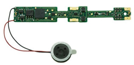
Sound decoders can actually be of any of the three form-factors described above. In addition to the issues shared with installation of non-sound decoders, you’ll face a new one: proper installation of the speaker. This increases the difficulty and the so-called ‘Plug’N’Play’ and ‘Drop-In’ sound decoders are likely not to operate properly, sound-wise, without significant work. In short, you’ll need to install a proper baffle to amplify the sound; a baffle does not come with the decoder and is specific to the locomotive. In some cases, it needs to be custom built. Also for models not initially designed for sound, you'll have to make room for the speaker - meaning cutting and grinding - or buy a replacement frame. So, unless you are a skilled modeler, you should probably buy your locomotives already DCC-sound-equipped if you want sound, to avoid any disappointment.
Drop-in decoders: from myth to reality
First of all, you need to remove the shell, and this can be tricky in some cases. Never use brute force; carefully read the manual and ask for advice if you really cannot figure it out. Sometimes, you’ll have to remove a hidden screw or remove the couplers. This is not hard, but it will keep you busy. But in many cases, if you simply loosen the shell from the chassis, it will remove smoothly.
An easy way to remove the shell (applicable to many North American models)
Then you’ll see the original analog (DC) printed circuit (PC) board that you need to replace. Now for the fun part!
Case 1: no need to disassemble the chassis
This is the case for most Kato models and for the most recent Walthers/Life-Like models (such as their GP-60 and GP-20 after 2011). There are usually a few pieces to remove, such as covers, board holder and motor contacts, but this is pretty easy to do. The PCB itself can be removed by pulling it backwards and the other way round to insert the decoder PCB itself.
There are however a few details to take care of:
- Contacts between PC board and chassis: for instance, the Digitrax replacement boards that I’ve used for my Walthers/Life-Like GP-20 and GP-60 are too thin. A drop of solder on the contact pad is recommended for proper contact – if not to make the whole thing work! Adding some tape on the frame can also help fill the gap and help press the PC board contacts on the chassis.
- LEDs on the PC board are too far away from the light pipe of the shell. This is the case when the replacement board comes with surface-mounted (tiny) LEDs whereas the original analog (DC) board uses classical LEDs with legs that deport the LED close to the light pipe. This is the major issue of replacement boards for the afore mentioned Walthers/Life-Like GP-20/GP-60.
- Some power pick-up metal strips must be isolated before installing the decoder. This is the case with a number of Kato models. The isolating material adds thickness to the strips and that thickness makes them more difficult to put back in place.


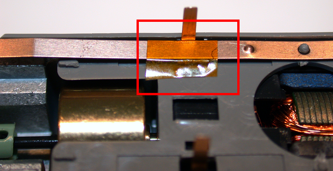
Case 2: partial or full disassembly of the chassis is required
Though the DCC decoder manufacturers claim the opposite, this is the case of most Atlas models. The original analog (DC) PCB cannot be removed without loosening the two half frames, but I would not recommend anyone just do that only.

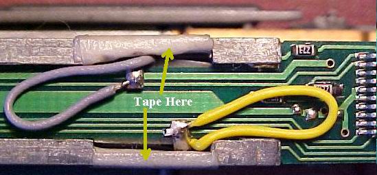
It is better to completely disassemble the chassis and isolate the upper part where there is a slight chance (bad luck?) that the motor contacts might touch the frame; you can use the Kapton tape that is usually provided with the decoder to do so, or any other isolating material, such as regular electrical tape.
After that, inserting the two motor contacts into the appropriate decoder PCB slots can be quite a challenge.
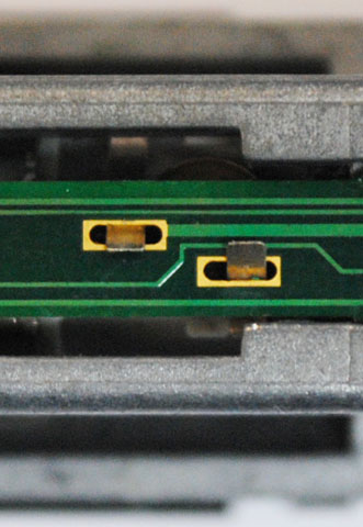
Some prefer to solder everything.
There are peculiar cases such as the Kato RDC for which Digitrax has designed their DN143K2 decoder. The installation of this decoder requires a lot of care.
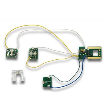
Case 3: some soldering is required.
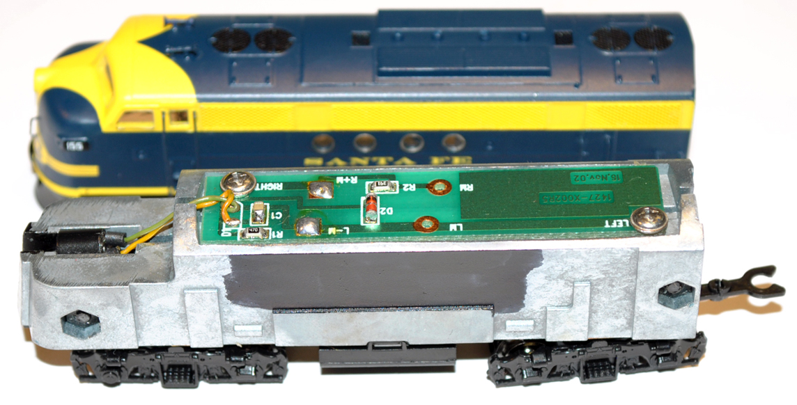
The flagship model in this category is the EMD F series by InterMountain, i.e. FT, F3, F7 and FP9. Since the front LED is inserted into the chassis and the LED is wired to the PC board, there is no way to avoid soldering. This is not very complicated, but you will need a soldering iron. Worse yet, InterMountain changed their its in 2014 and replaced ‘legs’ on the PCB, that could however pretend to be ‘Drop-in,’ left aside the front light wires, by wires. So more to wire and less and less ‘drop-in.’
Plug decoders: get access to the plug
Most of the examples in this section are for European models, as the plugged decoder is their preferred solution.
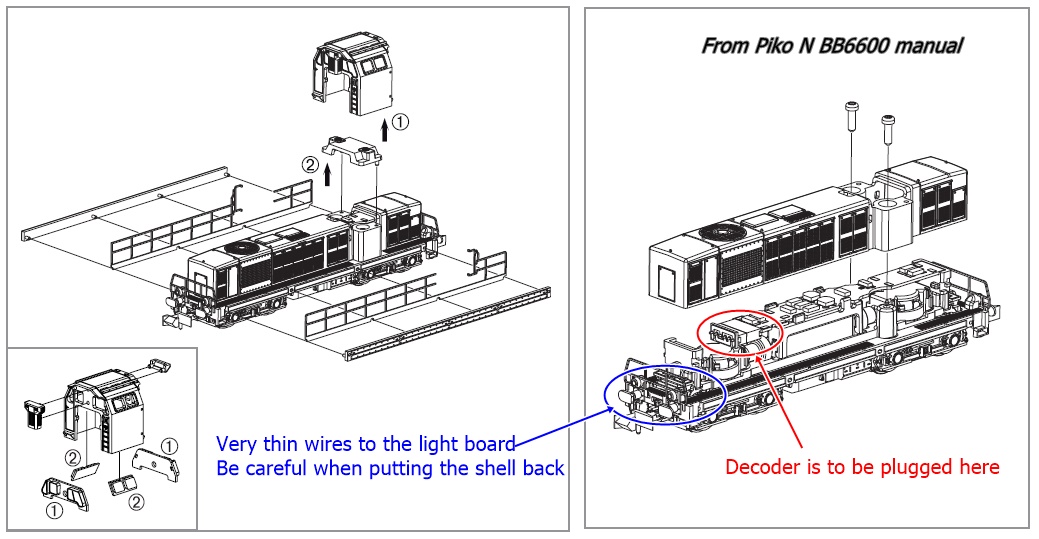
Removing the shell remains the first step. This can be quite complicated and cause damage to model components, like in the case of the Piko SNCF BB66000 series.

Case 1: Plug is on the top of the chassis
This is by far the easiest case and it really deserves the Plug’N’Play award. This is the case, for example, of:
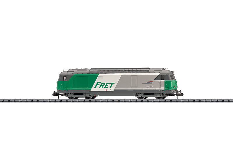
the Minitrix SNCF BB67000 (see page 10 of this manual),
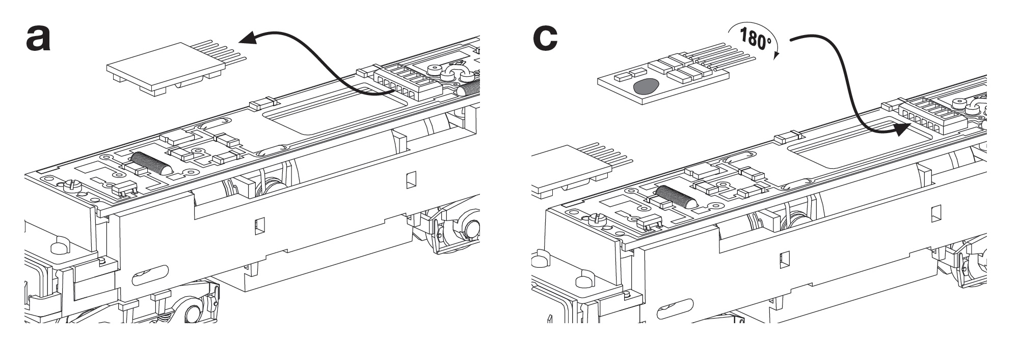
the Kato EMD Class 66 (example on pages 2 and 3 of the Digitrax DZ125IN)
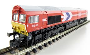
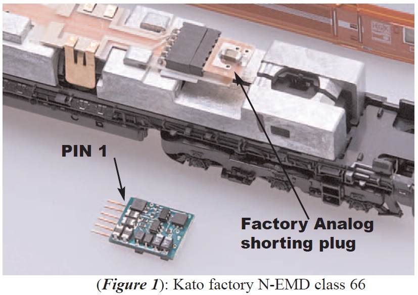
or the Fox Valley Models GE ES44AC (see installation page on TCS website).
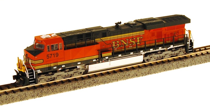
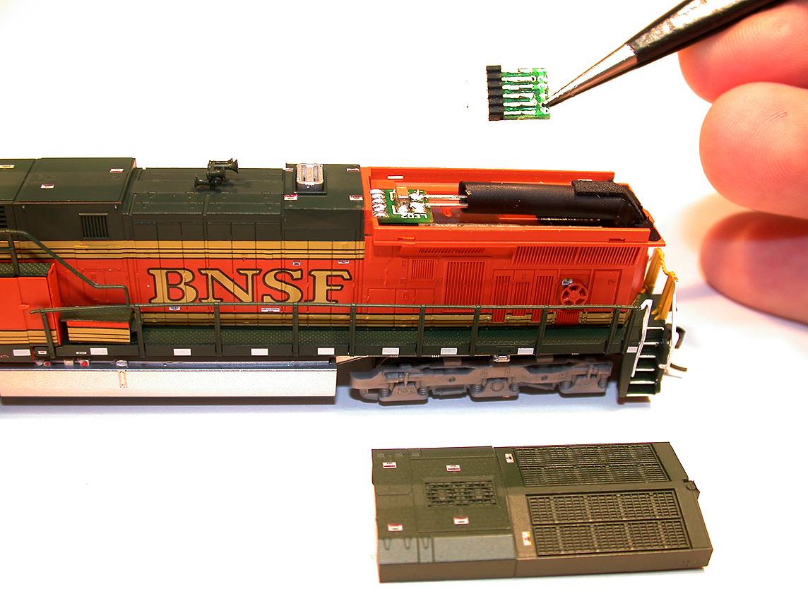
Note that the Fox Valley Model does not require full disassembly, but only removal of the fans cover.
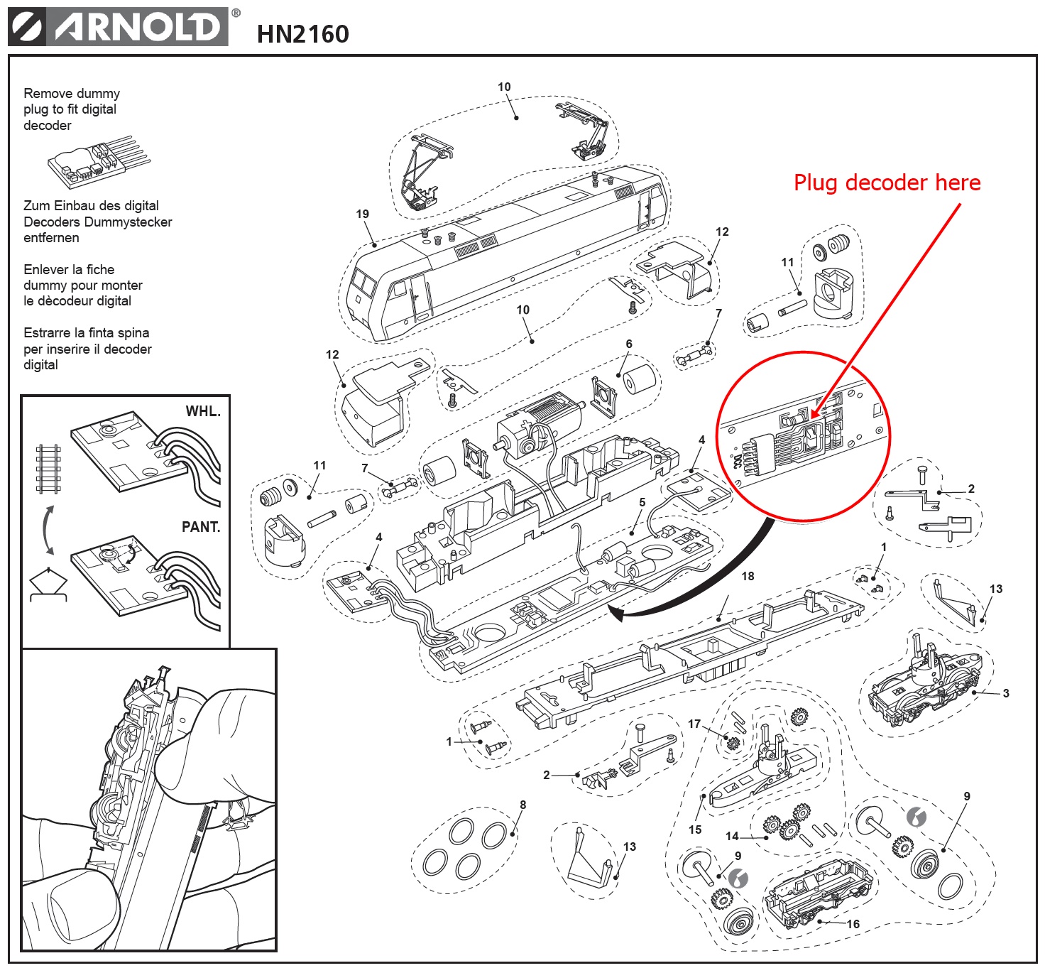
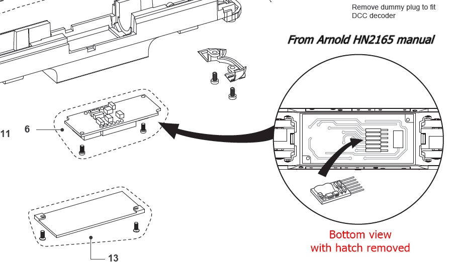
Another clever design is the Arnold Hornby Spanish Class 353. The prototype used to pull Talgo high-speed trains. As you can see on the assembly drawing, the decoder is installed on the bottom of the engine; but there is no need to disassemble everything. Instead you just need to remove a small hatch that is secured with 2 screws.

Case 2: Plug is somewhere else
"Somewhere else" means anywhere but on the top of the engine, so inevitably this requires a partial or full disassembly of the model. This can turn out to be not fun at all and certainly does not qualify as Plug’N’Play. I already mentioned above the Piko SNCF BB66000.
I can also mention the Arnold Hornby BR 152.
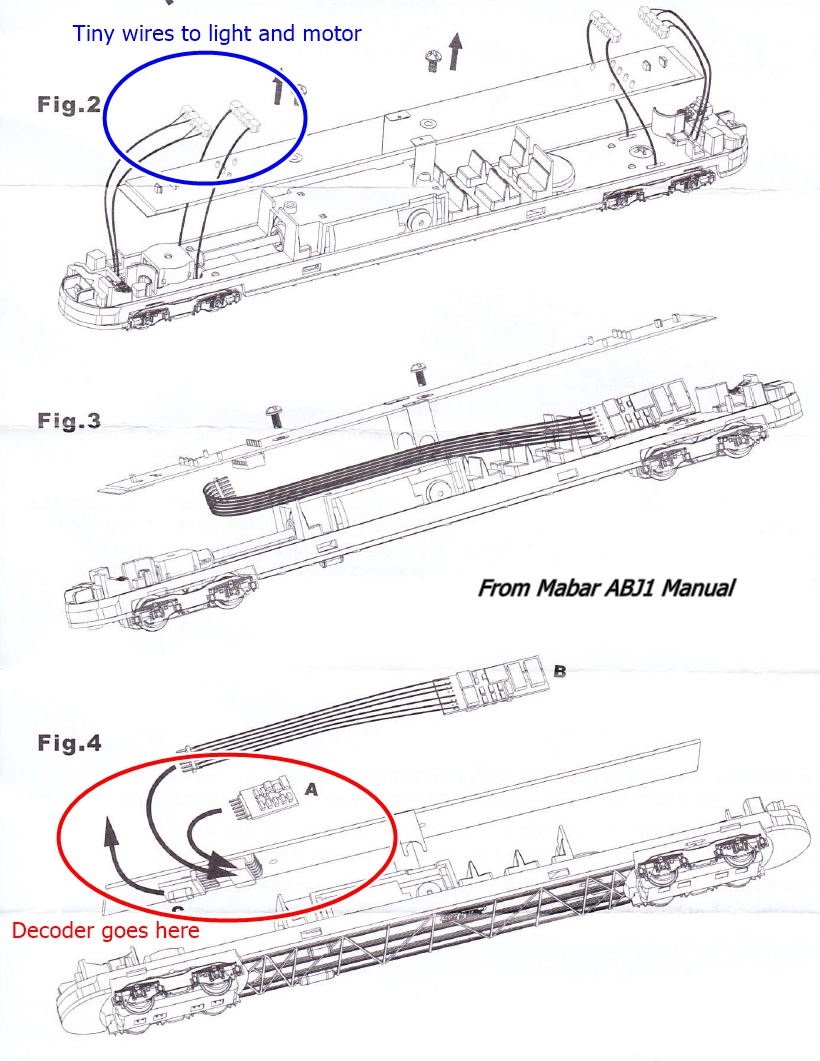
My last example in this category is the Mabar Renault ABJ1. The prototype is a well-known diesel rail car designed by Renault in the 1930s and could be seen on the French and Spanish networks into the early 1970s. The Spanish Mabar model is very fine; however, in order to keep the inside of the car clear of visible electronics, the design is such that the connection of the PC board to the lights is made by very tiny wires (see assembly drawing). No need for soldering, but connectors are very tiny and difficult to reassemble.

Missed opportunity or poor design?
Lastly, I’d like to mention one case that I consider a complete design failure, from a DCC perspective: the Life-Like GP38-2 released in 2006.
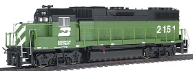
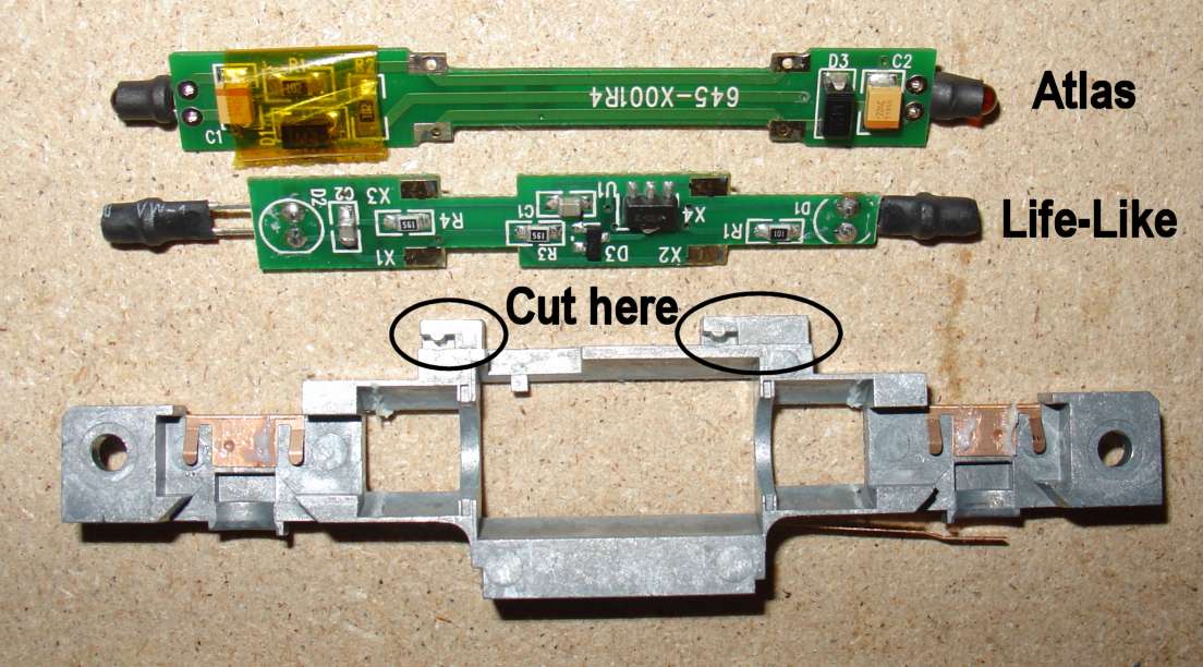
Though there is no mention of it on the box, the commercial claim was that the locomotive was ‘DCC Friendly’ in the sense that it had a split frame and a PC board. Yes but, the point is that the bottom motor contact is … at the bottom, i.e. without any metallic piece bringing it upwards and that the motor contacts go directly to the frame and not the PC board! Therefore, no DCC manufacturer ever designed a replacement board for it. I found a way to use a DCC replacement board however, but after several modifications to the frame and after wiring the motor to the board: this is explained in this article.
Bottom line
Please don’t get me wrong. This article is not about saying that adding a decoder to a locomotive is an herculean task. Instead, it is intended to give you some warning that this is not as an easy job as the manufacturers would like us to believe. However, a little practice and some attention to detail will certainly help you make the best of your engine in the DCC world.
And if you really don’t feel like gambling and installing a decoder yourself, go straight to the factory DCC-equipped models, which are now systematically offered by all manufacturers. For older models, even so-called ‘DCC Ready’ ones I’m confident your nearest hobby shop can offer you some assistance.
Credits
The copyright of this article is held by Alain LM, who is granting TroveStar with right to display it. This is an original article created based on the personal experience of the author with all mentioned models.
I want to warmly thank J. for proof-reading this article and fixing some awkward wording, as well as for the great improvement to the introduction.
All images are copyrighted by their owners.


